Posted on Leave a comment

Color Cameras in Microscopy

Believe it or not, people used film for taking pictures with microscopes – big, clunky cameras bolted to the microscopes, often with separate control units, and no way to preview the picture.  Just push the shutter release, cross your fingers and hope for the best – of course you wouldn’t know until you actually developed the film.  Fast forward a few decades and now cameras are ubiquitous – in our pockets, on our mobile phones and devices, even in our doorbells, all ready to capture the moment at a moment’s notice.  However, microscopy cameras are, indeed, different than that ubiquitous smart phone camera.  So why isn’t color imaging in microscopy as simple as a selfie?

Just as with cellphones, there are a wide variety of options for color cameras for microscopes. So how do you know which camera is best for you? Take a closer look at the technology.

Color technology

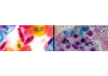
The most common technology to deliver a color image is a camera featuring a Bayer color mosaic filter (Fig. 1) – a red, green or blue filter on each pixel.  Note that with this most common filter arrangement, a given pixel only “sees” one color — this means that the resolution of a full-color image (in megapixels) is only 25% of the total megapixels available on that camera. A Bayer filter is the same technology used in most professional and consumer cameras, and the cameras in our mobile phones.  It is much more cost effective than 3-chip cameras (different sensor for red, green and blue) or cameras that use liquid filter-based color filters (take sequential images of red, green and blue, then overlay them).  Of course, your application may dictate which technology is most appropriate (i.e. speed, resolution, flexibility, simplicity).

Figure 1. Common Bayer filter pattern on camera color sensor (left panel), and the resulting color pattern recorded by the sensor pixels (right panel.  Images courtesy of https://en.wikipedia.org/wiki/Bayer_filter)

CCD or CMOS?

These acronyms refer to the technology used in the camera sensor.  Traditionally, CCD sensors delivered better quality images (i.e. less noise), and CMOS were cheaper and faster.  Newer CMOS technologies have greatly improved the image quality, and they’re still king when it comes to speed.  Even more recently, sensor manufacturers are concentrating their focus on CMOS technology, and the availability of CCD sensors is declining.

The turtle and the hare

If you are only imaging fixed slides or dead/inanimate objects, then there’s no need for a lightning fast camera – the specimen isn’t going anywhere, literally.  So, go for the best quality image possible, regardless of how fast or slow the camera.  On the other hand, if you are imaging living systems (i.e. live microorganisms) or a specimen in motion, then a faster “shutter speed” translates into better snapshots in time.  For live image streaming, displaying in front of an audience, or video capture, higher speeds are also preferred or necessary (i.e. 30 frames per second or faster is recommended), otherwise the audience could get motion sick.

Cameras with HDMI output generally provide faster frame rates for live preview, and often save the images to an internal storage device.  USB-output cameras used to have slower frame rates than their HDMI siblings, but the newer USB 3.0 cameras can stream at well over 60fps. USB cameras save directly to a PC while offering greater control of camera settings for image acquisition through software.  The latest arrivals are WiFi-connected cameras that take advantage of our mobile devices and a camera app for image acquisition.  Thanks to the latest wireless technologies, their frame rates are usually somewhere between those of HDMI and USB-output cameras.

More is better, right?

As general consumers of imaging technologies (first point-and-shoot cameras, now smart phones), we’re tricked into thinking “more” megapixels translate into better images.  NOT TRUE, at least not for microscopy!  Given the same size of the sensor, more pixels (or the little light-sensing component of a camera sensor) means smaller pixels which, in turn, means less “volume” in the pixel to sense light, thus reducing sensitivity.  Also due to the design of the technologies, there is a little more space between pixels in a CMOS sensor than a CCD sensor, therefore CMOS pixels tend to be smaller than those on a CCD.

And when it comes to sensitivity for lower light applications, [pixel] size does matter.  As I alluded to above, smaller pixels are less sensitive than larger pixels.  So for situations where sensitivity is important (i.e. fluorescence, darkfield, phase contrast), larger pixels (and consequently lower megapixel cameras) are actually preferred.  There is also an ideal pixel size for each microscope magnification, and this is determined based on the resolution of the microscope (please refer to the article “What’s the Deal with Megapixels?”  Suffice it to say that the higher the magnification, the larger the ideal pixel dimensions and, consequently, the fewer the pixels that fit on the sensor.

So, which camera is best?  That’s for you to decide (and our technical applications people can help).  Review the software and, of course, the image quality.  Consider how you will use the images (still images or live viewing), and the camera’s connectivity (HDMI, USB or WiFi).  One last word of advice: take the camera for a test drive.

Thanks for reading!

Posted on Leave a comment

Cleaning Microscope Optics

We all agree that a clean windshield or clean glasses work better and are more pleasing to look through. Microscopes work better when the optics are clean, too.  Dust and smears reduce the resolution, generate artifacts, and generally degrade the image, sometimes to the point of making the microscope useless.  Below are a few basic guidelines we use to clean microscope optics.  For best results, follow these steps in increasing order and NEVER soak the optic in any solvent!

  1. Use a puffer (Figure 1)
    • Remove surface dust by blowing air across it, and you only need a puffer or compressed air to do this.  This also avoids potential for scratching or smearing optical surfaces.
  1. Use lens tissue
    • Lens tissue has no lint, and lint can cause scratches.  We avoid using Kimwipes, too, as they may be abrasive.  Gently wipe an optical surface in a circular pattern, beginning in the center and spiraling outward (Figure 2).  Repeat. FYI, facial tissue contains a wetting agent that may add smears to the glass surface.
  1. Use water or warm breath
    • In combination with Step 2, a warm breath may be sufficient to remove the dust, debris, and some smears.  You may also wet the lens tissue slightly before wiping.  We will also wrap the lens tissue around a cotton-tipped applicator stick or Q-tip.  Alternatively, you can fold the lens tissue into a point (Figure 4a; courtesy of https://micro.magnet.fsu.edu).
  1. Use alcohol or lens cleaner (WEAR NITRILE GLOVES)
    • Alcohol or lens cleaning solution (Figure 3) is the next solvent after water/breath.  One of our favorites is Sparkle glass cleaner, but dilute this 1:1 with distilled or deionized water (a.k.a. Milli-Q water).  70% isopropanol or 70% ethanol is also acceptable, but not denatured alcohol.  Be careful when cleaning the eyepieces as these solvents may damage the rubber eyeshields.  Wrap lens tissue over applicator stick or Q-tip as above, and slightly dampen with solvent before wiping.  Work in circular/spiral motion from the center outward.  Repeat.
  1. Use stronger solvents (WEAR APPROPRIATE GLOVES), or seek professional help
    • In some cases, and with some stuck-on substances like dried-on immersion oil, you may need to use other solvents such as xylol or a 1:1 mixture of ether-ethanol.  IMPOTRANT! DO NOT SOAK THE OBJECTIVE IN THE SOLVENT as this may soften the cement securing the lens elements.  Other organic solvents may also be used for more stubborn crud (Residual Oil Remover, pure petroleum ether, etc.).  Follow same procedure as in Step 4, and use sparingly!

One final tip.  It is easier to inspect and clean objectives if they are removed from the microscope.  Remove one of the eyepieces and look through it the “wrong way” (e.g. from the back; Figure 4b) at the lens – – it’s a handy 10x magnifier!  With a few seconds of practice, you can see smears, dust and even damage to the lens.

Enjoy your clean microscope and, to maintain peak performance, remember to clean those optics on a regular basis.

Posted on Leave a comment

Demystifying Numerical Aperture

We are often asked to recommend the objectives for a microscope.  The objective sits closest to the specimen, and is an integral component of the microscope and crucial to delivering an acceptable image of the specimen.  All the information you need to know is written right on the barrel of the objective: flatness correction, magnification, Numerical Aperture, immersion medium, optical path design, and whether to use with or without a coverglass.  One of the more confusing criteria, however, is Numerical Aperture.  In this brief article, I’ll attempt to demystify Numerical Aperture, and how to get the most out of it.

Very simplistically, Numerical Aperture (“NA”) is the ability of an objective lens to collect light, and it’s written on the objective just after the magnification (Figure 1).  A higher angle of light = a higher NA (see Figure 2).  Additional light means more information, which means better resolution.  So the higher the NA, the better the optical resolution.  But it’s not as easy as moving closer to the specimen.

In order to take maximum advantage of the objective’s NA, the condenser should be adjusted to match – this adjustment is one step of Köhler Alignment.  Thankfully most condensers have an aperture adjustment for this purpose (see Figure. 3).  Since the NA changes every time you change objectives on a microscope (objectives with higher magnification typically have higher NA), the condenser should also be adjusted – this is literally a 2 second adjustment, and can make a HUGE difference in the image and resolution.  We’ll review Köhler Alignment in another article.

Let’s say that two objectives have the same magnification but different NAs. The one with higher NA will typically cost more.  And to get an NA of 1.0 or higher, you’ll need an immersion objective that requires some other medium than air (typically oil, water, glycerin, or silicon oil) to be placed between the objective and the coverglass above the specimen.  This additional medium bends (“refracts”) more light (therefore, more information) into the objective lens, thereby increasing resolution. Note that immersion objectives are specifically designed for particular immersion media, and no objective should be used with an immersion medium for which it was not intended – – this will void any warranty, and you won’t get the results you hoped for.

Numerical Aperture = n sin θ

where n is the refractive index of the medium between the objective and the coverglass, and θ  is the ½ angle of light collected by the objective lens (refer to Fig. 2).  Air has a refractive index of approximately 1.0 and typical immersion oil has a refractive index of 1.51.  You can see how oil is needed for an NA > 1.0.  Therefore in order to have an NA greater than 1.0, you’ll need to use an immersion medium with a refractive index higher than 1.0.

Objectives of the same magnification but different NAs will give different results.  A higher NA objective, when the microscope is properly adjusted, will have higher resolution and deliver a crisper image.  The trade off is that the depth of focus becomes shallower as resolution increases.  So if you want to have more of the specimen in focus, you may want to choose an objective with lower NA.

Finally, higher NA doesn’t necessarily translate into a better image.  Other optical qualities must be considered (e.g. correction for field curvature, chromatic aberration, spherical aberration, etc.), all topics for another time.

Thanks for reading!